Cometary activity: gas and dust outflow

← back to the research overview
1. Introduction
Comets are small solar system bodies (typically 1-10 km) containing a significant amount of ices (primarily H2O, CO2, and CO). There is a general consensus that comets formed in an original reservoir between 20-40 au from the Sun. From there, they were scattered into the current trans-Neptunian region. The so-called scattered disk and Oort cloud are the source reservoirs for Jupiter family comets and long-period comets, respectively. When comets enter the inner Solar System, their ices begin to sublimate. The sublimated gas escapes the comet and rips dust particles with it. The gas and dust around a comet form the so-called comae.
2. A model of the cometary gas and dust environment
I have built a self-consistent simulation pipeline to model cometary nuclei’s gas and dust emission. It includes the inner comae’s relevant physical processes (within tens of kilometres above the cometary surface). The described methods apply to any comet. We have focussed on understanding multi-instrument results from the European Space Agency’s (ESA) Rosetta mission to comet 67P/Churyumov-Gerasimenko (hereafter 67P). The results using this modelling approach have been published in Marschall et al. (2016), Marschall et al. (2017), Gerig et al. (2018), Marschall et al. (2020a), Marschall et al. (2020b), Gerig et al. (2020), and Pinzón-Rodríguez et al. (2021). I have also co-authored two review papers on how we can use models to understand the surface of comets. There are published in Marschall et al. (2020c) and Marschall et al. (2023).
This page provides a brief overview of the different steps involved in our modelling pipeline.
The physics of the outflow from cometary surfaces has been the subject of intense study for more than 40 years. Ice sublimating into a vacuum forms a non-equilibrium boundary layer, the “Knudsen layer” (Kn-layer), with a scale height of ~20 mean free paths (MFP). If the production rate is low, the Kn-layer becomes infinitely thick, and the velocity distribution function (VDF) remains strongly non-Maxwellian. Nowadays, the state-of-the-art method to study gas flows inside non-equilibrium regions is the Direct Simulation Monte Carlo (DSMC) method. After obtaining a steady-state gas solution, we introduce dust particles into the flow to determine the physical parameters of the dust coma (i.e. dust number densities).
2.1. The shape model
The starting point of all our simulations is a shape model of the comet. In the case of 67P, we use the SHAP7 model by Preusker et al. (2017) shown in the animation. These shape models consist of triangles, called surface facets. The full-resolution shape model of SHAP7 has more than 40 million facets. This is far greater than we can use in our simulation due to computational costs. We thus use a reduced model with around 400,000 facets instead.
2.2. The illumination model
Solar insolation is the primary driver of cometary activity by providing the energy to sublimate ice at or close to the surface. We must determine the heat input before calculating the gas production rate from the cometary surface. The distance to the Sun and the angle between the normal of the local surface and the direction to the Sun, the so-called incidence angle, 
For a specific point in time, we can calculate the position of the Sun relative to the comet. Our illumination model then calculates the incidence angles for every facet, considering shadows cast by other parts of the cometary shape onto itself. The animation on the left shows one of the results. It illustrates how the illumination conditions, including the shadows, change as the nucleus rotates. The Sun in this animation is located toward the top centre of the frame.
2.3 The thermal model
Now that we have calculated the Sunlight’s incidence angle to the comet’s surface, we can use a thermal model to calculate the surface temperature and gas production rate from each surface facet. We use a simple thermal model omitting thermal conductivity (i.e. the thermal inertia was set to zero. We note that Gulkis et al. (2015), Schloerb et al. (2015), and Choukroun et al. (2015) measured low values consistent with values seen at 9P/Tempel 1.
We have thus imposed a simple thermal balance for each surface facet: 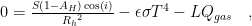


2.4 The gas dynamics model
Now that we know which facet emits how many gas particles at which temperature, we can apply a gas dynamics calculation to determine where the molecules flow to in 3D space. Because the production rate at comet 67P spans large ranges from low to high, the gas flow, in principle, transitions from either fluid or collisional to a free adiabatic outflow. Thus, our preferred method is Direct Simulation Monte Carlo (DSMC) because it covers all these regimes. It has the disadvantage of being very computationally expensive. For high production rates, a fluid approach might be computationally more economical.
The code we are using, named PDSC++ (Su 2013), was previously used to model the water vapour distribution in the vicinity of comet 9P/Tempel 1 (Finklenburg et al. 2014) and is based on the PDSC code developed by Wu and co-workers (Wu et al 2003, 2004, 2005). PDSC++ allows the simulation of 2D, 2D-axisymmetric, and 3D flows on hybrid unstructured grids. The code has been parallelised, allowing a much larger number of cells. It has been implemented on several clusters in Bern (Switzerland) and Taiwan. The code is especially useful because it can treat large density gradients by implementing a variable time step and a transient adaptive sub-cell technique to increase computational speed and accuracy in high-density regions (Finklenburg et al. 2014, Finklenburg 2014).

Within the DSMC code, a smaller number of simulation particles represent the actual gas molecules. These simulation particles are used to generate a statistical representation of the flow. The microscopic behaviour of the simulation molecules is separated into a translational step and a collision step. In one collision step, the collision pairs are chosen randomly from all the molecules within one cell. Macroscopic gas properties such as number density, velocity, and temperature are calculated by averaging the appropriate quantity of all simulation molecules in the respective sampling cell.
Even though the code can fully treat multi-species flows, in most of our work, we consider water only because it is by far the most dominant species in the coma of 67P (Haessig et al. 2015). In addition, we are interested in the dynamics within the first kilometres of the gas coma above the cometary surface. Thus, we do not need chemistry in our gas model. Processes such as photo-dissociation and ionisation occur on much longer time scales.
The results of this model provide gas number densities, temperatures, and speeds in 3D space around the comet out to the edge of our simulation domain (usually 10-20 km from the nucleus centre). An example result can be seen in the figure illustrating two slices through the 3D gas field showing the gas speed [m s-1]. The nucleus shows the illumination of the surface at the time of this simulation. The results from these simulations can be compared to several instruments on board Rosetta, including the Rosetta Orbiter Spectrometer for Ion and Neutral Analysis (ROSINA), the Microwave Instrument for the Rosetta Orbiter (MIRO), and the Visible and Infrared Thermal Imaging Spectrometer (VIRTIS). By comparing simulation results and measurements, we can constrain the gas emission regions at the surface and the physical processes occurring during the expansion of the gas from the surface into the vacuum. Furthermore, these kinds of simulations also provide a powerful tool to determine the limits of data interpretation possible.
2.5 The dust dynamics model
Given a gas flow field, we can now study the motion of dust particles in this flow. These two dominant forces govern the motion of the dust: the force produced by the gas drag on the dust particles to accelerate them away from the surface, and the gravity of the nucleus as an opposing force. The dust follows, though in a complex way, the gas flows from the nucleus. If the gas flow is perpendicular to the surface, so is the motion of the dust particles within the first meters above the surface. Lateral flows in areas with large gas production rate gradients (such as close to the terminator) are possible and thus also result in lateral dust flows close to the surface.
We treat the dust grains as test particles and consider them to be spherical. There are strong indications, though, that the larger dust grains are porous and fluffy aggregates (Kolokolova et al. 2010, Schulz et al. 2015, Rotundi et al. 2015, Langevin et al. 2016, Bentley et al. 2016, and Mannel et al. 2016). We justify treating the dust as spherical particles because the main parameters influencing the dust trajectory are the mass and cross-section. Therefore, our dust particles must be understood as effective spheres with the respective cross-section and mass of the dust particles they represent. At this point, we still know little about the physical properties of the dust particles (such as their shape and density) and, perhaps more importantly, about how they orient themselves in the gas flow (Ivanovski et al. 2017).
The equation of motion for each dust grain which has mass 


where 


By injecting millions of dust particles of different sizes into the gas flow and solving their equation of motion to determine their trajectories, we can determine the local properties of the dust flow within the inner coma (i.e. dust number densities). The animation on the right illustrates how dust particles travel through space. These results can be compared to several instruments onboard Rosetta, including the Optical, Spectroscopic, and Infrared Remote Imaging System (OSIRIS), the Grain Impact Analyser and Dust Accumulator (GIADA), the Cometary Secondary Ion Mass Analyser (COSIMA), and the Micro-Imaging Dust Analysis System (MIDAS).